Armoured
Systems
System Mechanics
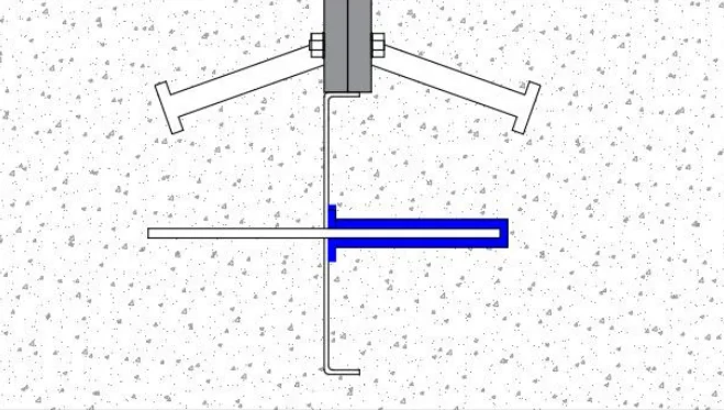
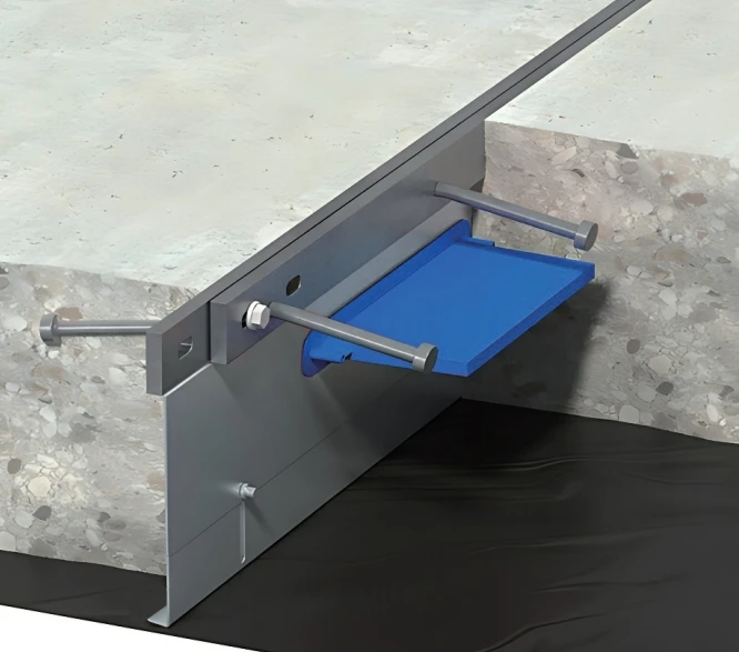
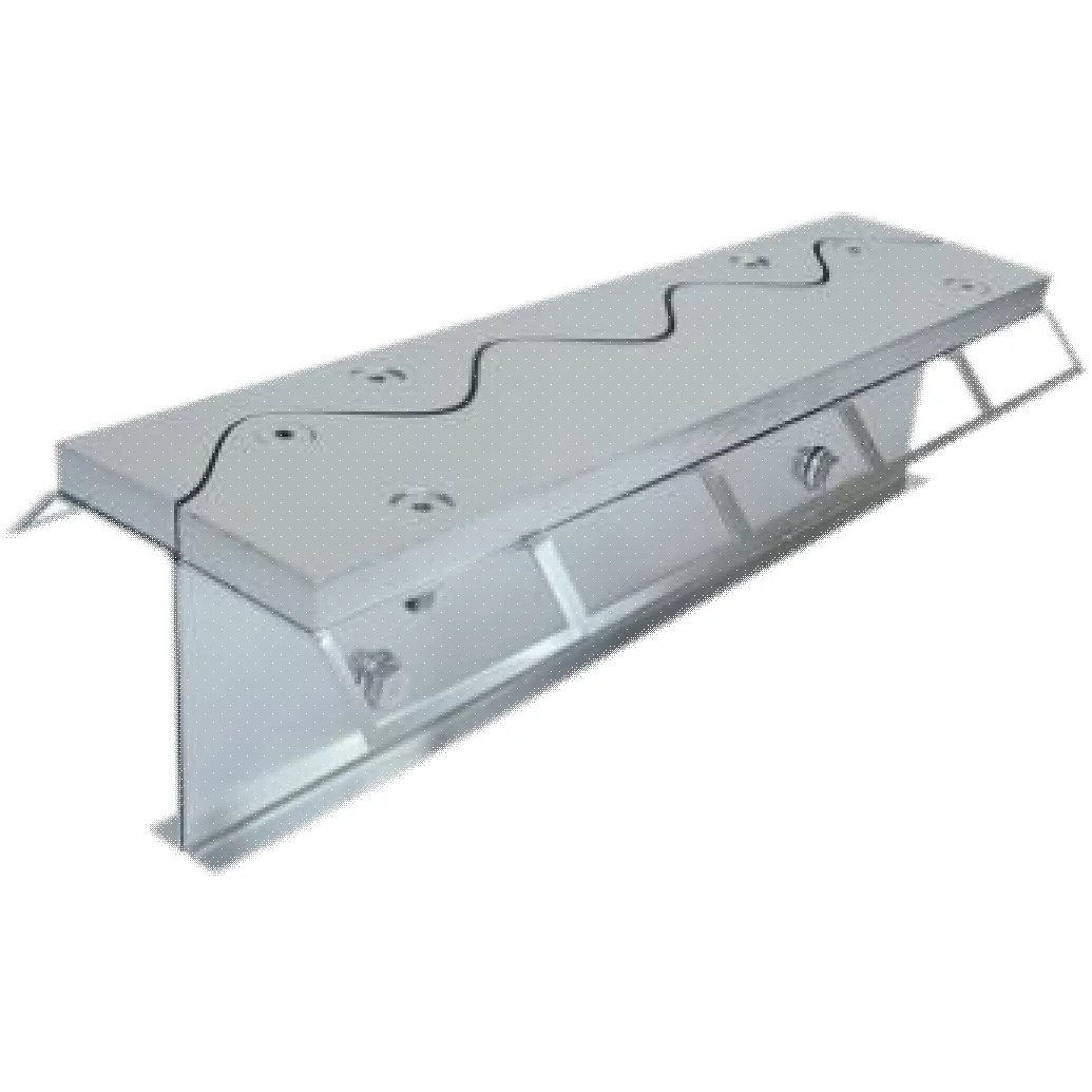
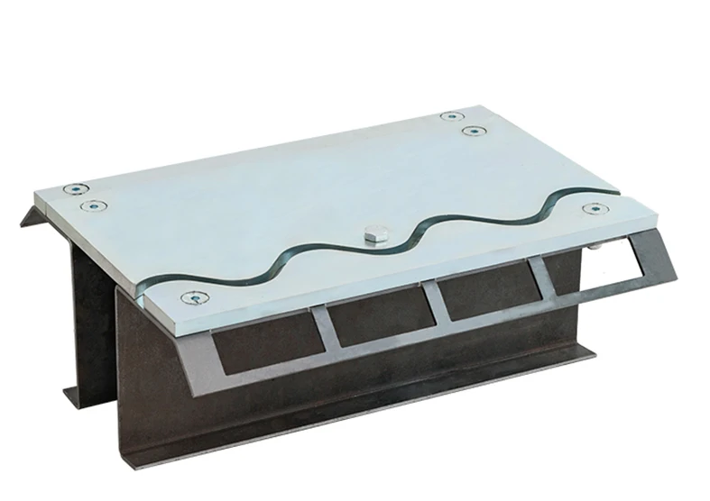
Armoured joints work in synergy to provide active anti-shear, positioning, and anchoring. By creating a high-straightness metal shield at the joint edge, we ensure the concrete remains perfectly linear through its lifecycle.
These systems utilize sleeved dowel plates that allow free longitudinal (20mm) and transverse (10mm) movement, fully complying with UK TR34.4 global standards.
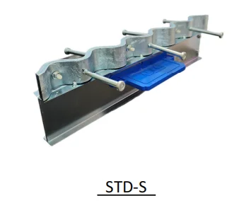
Load Transfer: High-strength plates bridge the joint, ensuring vertical load continuity even when slabs expand.
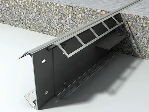
Edge Reinforcement: Galvanized steel profiles provide a permanent shield against mechanical impact from heavy logistics equipment.
Active Alignment: Standardizes joint opening during concrete shrinkage while maintaining a perfectly level floor surface.

92% Failure Origin
Industrial flooring statistics reveal that 92% of problems are joint-related. Proper isolation and modular construction are essential for high-performance slabs.
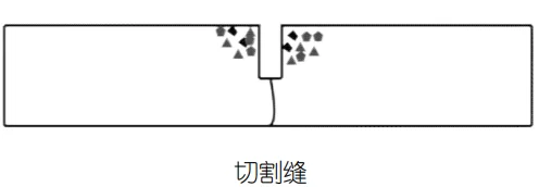
Common expansion solution but lacks edge reinforcement. Unprotected edges are high-risk zones under heavy traffic.
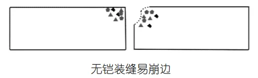
Caused by aggregate sinking, joint vibration, and insufficient edge strength. Leads to severe concrete crumbling.
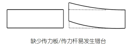
Lack of load transfer plates leads to "stepping" between slabs. Severely impacts AGV robot tires and precision ops.
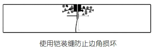
Prevents vehicle wheels from direct crushing. Effective elimination of edge spalling and long-term joint opening issues.
Effectively absorbs thermal and drying shrinkage stresses, preventing large-scale slab cracks.
Load transfer plates buffer external settlement and uneven loads, maintaining surface levelness.
Disperses external impact forces, protecting the concrete matrix and extending total service life.
Permanent galvanized steel shielding prevents heavy logistics equipment from damaging joint edges.
Collection Index
PRECISION
WITHOUT BORDERS.
VALENCIA TECHNOLOGY HUB | DEZHOU MANUFACTURING CENTER
Our reach extends from our core R&D center in Valencia, Spain to our high-capacity production facilities in China. This synergy allows us to deliver European-standard precision with global scale logistics.
Layout Principles
Installation Sequence
Use laser levels to calibrate elevation.
Fix to subgrade via rebar supports.
Remove temporary fixing rebars before adjacent pour.
Clean and apply joint filler after curing.